
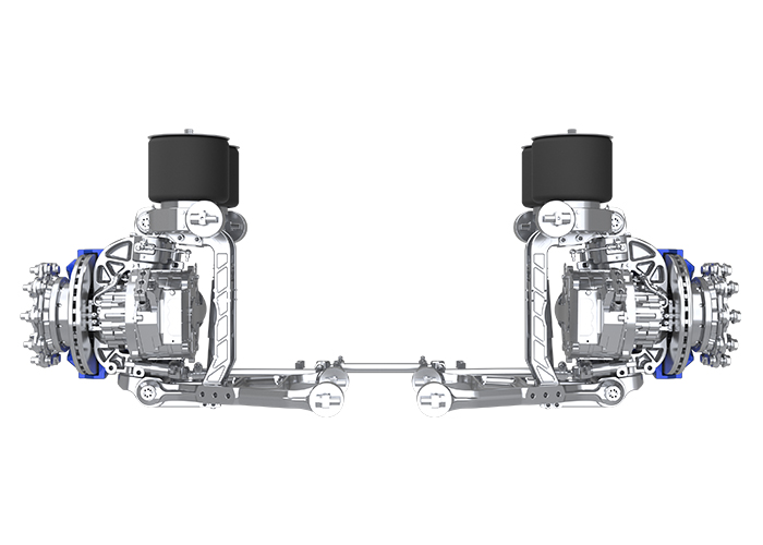
An e-axle does not lose efficiency in one dramatic event. Energy is consumed through gear mesh, bearing drag, seal friction, oil churning, rotor losses, inverter switching, and thermal-management demand. These “mechanical parasites” become especially important at light load, where fixed losses represent a larger share of the input power. Achieving more than 95% system efficiency is possible only at defined operating points and with the motor, inverter, gearbox, lubrication, housing, and controls engineered as one assembly. Buyers should examine the full efficiency map rather than accept a single peak figure.
Where do the largest parasitic losses occur inside an e-axle?
Losses are distributed across electrical, mechanical, and thermal subsystems. A design change that improves one area can worsen another, so optimization must consider the complete operating range.
How do gears, bearings, and seals consume energy?
Gear contact creates sliding and rolling friction. Tooth geometry, surface finish, alignment, load distribution, and lubricant viscosity determine how much power becomes heat. Excessive preload in bearings raises drag, while insufficient preload can increase vibration and misalignment.
Radial shaft seals also create continuous friction. Their effect may appear small at rated power but becomes significant during low-torque cruising. Seal lip material, contact pressure, shaft finish, and lubrication should therefore be selected for the actual speed and temperature range.
Why do oil churning and windage matter?
Rotating gears and shafts accelerate oil and air inside the housing. Overfilling, high viscosity, poor oil return, and unnecessary rotating surface area increase churning losses. At high speed, windage and oil aeration can also raise temperature and reduce lubrication stability.
A smaller oil volume is not automatically better. Bearings and gear contacts still need reliable lubrication during acceleration, grade changes, and cold starts. The design must reduce drag without creating starvation.
How can a streamlined drive assembly raise system efficiency?
A streamlined assembly shortens the power path, removes unnecessary interfaces, and places components where loads can travel through the housing with limited distortion. Integration is useful only when it improves alignment, thermal control, and serviceability.
What does mechanical integration change?
Combining the motor, reduction gear, differential, and inverter can reduce shafts, couplings, bearings, fasteners, and separate housings. Fewer interfaces may lower mass and alignment error. A compact structure can also shorten electrical connections and reduce coolant routing.
However, integration concentrates heat and vibration. Housing stiffness, bearing seats, gear-center distance, and thermal expansion require tighter control. A lighter housing that distorts under torque may increase gear loss and noise.
Which transmission choices influence efficiency most?
Single-speed reduction is common because it limits shift hardware and control complexity. Ratio selection must balance launch torque, gradeability, motor speed, highway efficiency, and maximum vehicle speed. A ratio chosen only for peak efficiency may push the motor into less efficient regions during normal driving.
Gear tooth microgeometry, bearing arrangement, differential design, and lubrication method should be optimized together. Surface finishing can reduce friction, but it cannot compensate for poor load distribution or shaft deflection.
How should “over 95% system efficiency” be measured and interpreted?
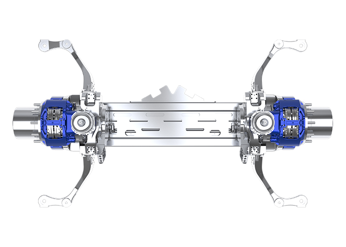
A peak value is meaningful only when the measurement boundary and test conditions are clear. Motor-only efficiency, inverter efficiency, gearbox efficiency, and complete e-axle efficiency are not interchangeable.
What belongs inside the measurement boundary?
For a complete e-axle, electrical input should be measured at the inverter DC terminals and mechanical output at the axle or output shafts. Auxiliary loads such as oil pumps or coolant pumps should be included when they are required for operation.
The report should state voltage, torque, speed, oil temperature, coolant condition, warm-up procedure, and whether the result is motoring or regenerative. Without these details, two efficiency claims cannot be compared reliably.
Why is an efficiency map more useful than one number?
Peak efficiency usually occurs in a limited speed-and-torque region. Urban launch, highway cruise, hill climbing, cold operation, and regeneration occupy different areas of the map. A design with a slightly lower peak may consume less energy over the actual duty cycle if its efficient region is broader.
Buyers should request map data, operating-point coverage, and test repeatability. Vehicle mass, tire losses, and aerodynamic drag should not be mixed into the e-axle result.
Which manufacturing and validation controls protect efficiency in production?
Prototype efficiency can disappear when production variation changes gear contact, bearing preload, rotor position, inverter calibration, or oil fill. Critical dimensions and process settings need measurable limits.
Which production details deserve close inspection?
Inspect gear lead and profile, runout, shaft concentricity, bearing-seat dimensions, preload, seal installation, rotor-stator air gap, resolver position, busbar connections, and oil quantity. Assembly cleanliness matters because debris can damage bearings or alter gear contact.
End-of-line testing should cover electrical insulation, rotation direction, noise, vibration, torque response, current, temperature, and leakage. Efficiency sampling should use the same boundary and conditioning method as development testing.
What failure modes can increase losses before complete failure?
Bearing damage, gear misalignment, excessive seal drag, oil foaming, cooling restrictions, and inverter calibration drift, are examples of causes where the equipment energy consumption can increase while the unit is operating. The signs can be observed during a rise in temperature, noisy operation, higher current consumption, or reduced coast down time.
The test procedures for determining the durability should include a number of repeated torque reversals, prolonged running at high torque, thermal cycling, grade simulation, and lubrication aging. The test results should be compared with the original equipment data by evaluating the wear.
What should buyers compare when evaluating e-axle suppliers?
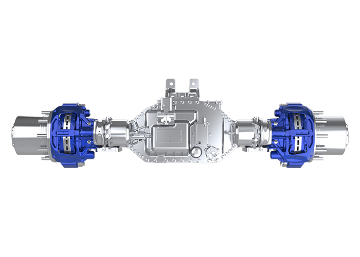
Supplier evaluation should move beyond peak power and peak efficiency. The buyer needs evidence that the proposed unit fits the vehicle duty cycle, packaging envelope, thermal system, control architecture, and production volume.
Which technical documents support a sound comparison?
Request a set of efficiency maps at various operating states. Ask to provide torque/speed curves, gear ratio, continuous and peak ratings and derating, thermal limits and recommended lubrication and cooling, mass, size, mounting loads, noise spectra, and test validation. Clarify the definitions of continuous, peak, and derating.
Interface control documents should cover high-voltage connections, communication, coolant ports, output shafts, mounts, sensors, and diagnostic functions. Changes to any of these can affect vehicle integration.
Which commercial controls reduce repeat-order risk?
Approve drawings, bill of materials, software version, calibration, critical-component list, test limits, and traceability before proceeding to production. The supplier must notify the buyer of any changes in gears, bearings, seals, semiconductor modules, magnets, lubricants, sensors, or housing processes.
Quotations shall include tooling, stage of development at which samples are due, acceptance responsibility, lead time, service parts, warranty, and change control. Production capacity is useful only when the approved configuration remains stable.
How can an e-axle supplier support high-efficiency drive development?
Hangzhou Çağdaş Elektrikli Sürüş Teknolojisi Şirketi is developing advanced e-axle solutions for electric vehicle applications. Inputs to the project shall include vehicle mass, wheel size, targeted accelerations, gradeability, speed, duty cycle, DC voltage, cooling, packaging, and axle-load requirements. The technical assessment shall address motor type, inverter rating, reduction ratio, differential, lubrication, thermal linkages, mounting interfaces, control functions, and torque, speed, and efficiency performance envelope. Testing of samples shall be carried out to verify torque response, temperatures, noise, and vibration performance characteristics as well as leakage tests, electrical safety, and efficiency maps. Prior to production validation, both parties shall agree on drawings, software, calibration, and critical components, test specifications, traceability requirements, and change notification procedures for vehicle integration and production control.
Çözüm
Eliminating mechanical parasites requires disciplined system engineering rather than one low-friction component. Gear geometry, bearing preload, seal drag, lubrication, housing stiffness, motor control, inverter losses, and thermal management all shape e-axle efficiency. More than 95% system efficiency should be treated as a measured operating-point result, not a universal condition. Buyers should compare complete efficiency maps, verify test boundaries, and control production variables that can turn small losses into meaningful vehicle energy consumption.
Sıkça Sorulan Sorular
1. Can an e-axle maintain over 95% efficiency at every operating point?
No. Efficiency changes with torque, speed, voltage, temperature, lubrication, and auxiliary loads. A unit may exceed 95% in selected regions while operating below that level elsewhere.
2. Which mechanical losses matter most in an e-axle?
Gear mesh, bearing drag, seal friction, oil churning, windage, and misalignment are major sources. Their relative importance changes with speed, torque, temperature, and lubricant condition.
3. Why should buyers request a complete e-axle efficiency map?
A map shows performance across the usable torque-speed range. It reveals whether high efficiency covers the real duty cycle or appears only at one favorable test point.
4. How can oil selection affect e-axle efficiency?
Viscosity influences churning, bearing drag, gear-film formation, and cold-start behavior. The lubricant must reduce friction while maintaining wear protection, thermal stability, and material compatibility requirements.
5. What production controls help preserve high e-axle efficiency?
Control gear geometry, shaft alignment, bearing preload, seal installation, air gap, resolver position, oil fill, inverter calibration, cooling flow, and end-of-line test limits across repeat orders.